Ok, this time its no retro project, but a rather useful tool to measure your temperatue at home over a longer period of time. I had trouble with my heating devices at home and so I wanted to record and present temperature curves of various rooms to show that something is wrong…
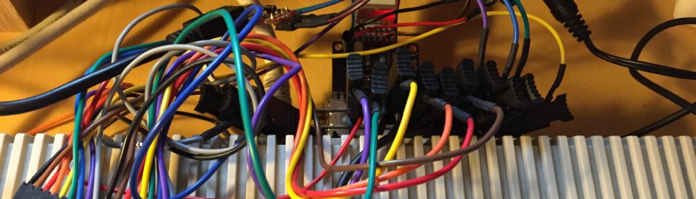
This was a friday night project and done in a few hours (some might call it a hardware hack – but it works fairly stable for weeks now!). All you need is an Arduino 2009 Board, a Logger Shield, a push button, 2 1k resistors, and a DS18S20 temperature sensor. With these ingredients I was able to build the following compact temperature logger:

Arduino and Logger Shield: Temperature Logger
The logger samples the temperature every 10s and gives you a digital temperature value with +/-0.5 degree Celsius precision. It has a RTC (real-time-clock) on board that time stamps every measurement. Addionally, the SD card allows you to store the temperature samples in log files.
The logger has two modes of operation: Either directly read the temperature via a Mac/PC connected via the virtual serial port available on USB or write a temperature log onto the SD card. The latter mode allows you to use the device stand alone in any room without the need to directly connect your computer.
Read on for the full build and usage instructions…
1. Hardware
You need:
- an Arduino board (I use an Arduino 2009 but UNO will be fine, too)
- an Adafruit Logger Shield
- a push button (to toggle SD card recording)
- a DS18S20 digital temperature sensor
- 2 1k resistors
Use the prototyping area of the Logger Shield to attach the push button and the DS18S20. The following fritzing.org schematic shows you the required connections:
 Note: the LEDs and the associated resistors are already available on the logger shield. You only have to connect them to the Arduino on DIGITAL 3 and DIGITAL 4 pins. The LED pins have connectors right beside the two DIGITAL ports. So two small wire bridges will connect them. The push button is connected to DIGITAL 2 and the temperature sensors data channel to DIGITAL 7. The temperate one-wire bus needs a 1k pull up to 5V while the push button uses a 1k pull down resistor.
Here is a summary of the connected digital ports:
- DIGITAL 2: push button input
- DIGITAL 3: LED (green) output
- DIGITAL 4: LED (red) output
- DIGITAL 7: temperature sensors DS18S20 DQ data channel
That’s it for the hardware… and don’t forget to add a battery for the RTC (real time clock).
2. Software
2.1 Firmware
The firmware is hosted on my github site:
- GitHub: ardu.git
-
git clone git://github.com/cnvogelg/ardu.git
Simply clone this repository and have a look in the datalog directory:
The file datalog.ino is an Arduino IDE sketch you can directly open there.
Note: the sketch requires the RTC and SD FAT FS library that is available at Ladyada for the Logger Shield: see the Logger Shied Download page for details and install the libraries first!
Open the sketch and flash it on your device…
2.2 Configuration
Before you can use the data logger you have to configure it:
- In the Arduino IDE open the serial monitor (Tools -> Serial Monitor) with 57000 Baud and Line Ending Both NL+CR
- Insert a FAT formatted SD card and power the device
- If the green LED is enabled then everything is fine and SD and temperature sensor was detected. You can see the serial number of your sensor:
DS18S20: 10 83 B4 8D 2 8 0
- If the red LED blinks then an error has occurred:
- Either the sensor was not detected:
FATAL: ADDR?
-
- Or the SD card was not found:
FATAL: SD
-
- In both cases have a look at your wiring or your card to fix this…
Now we are ready to set up the RTC (real time clock):
- You can enter commands in the Serial Monitor and send them to the device
- The following commands are supported:
- ‘r’ – read clock (load time and date from RTC chip and print it)
- ‘a’ – adjust clock (save the current values for year, month, day, hour, minutes, seconds to RTC chip)
- ‘y’ <nnnn> – set year: 2012 …
- ‘m’ <nn> – set month: 01 .. 12
- ‘d’ <nn> – set day of month: 01 .. 31
- ‘H’ <nn> – set hour: 00 .. 23
- ‘M’ <nn> – set minute: 00 .. 59
- ‘S’ <nn> – set seconds: 00 .. 59
- ‘o’ – open log on SD card for writing
- ‘c’ – close open log on SD card and stop writing
- ‘D’ <nnnn> – interval of measurements in seconds. default: 10s
- So for setting up the clock to: 28.11.2012 18:34:20 you would enter:
y2012
m11
d28
H18
M34
S20
a
- Now your RTC is set up and you should see incoming measurements like this one
t: 2012.11.18 19:39:03 50A93957 +024.50 0189
t: 2012.11.18 19:39:13 50A93961 +024.50 0189
t: 2012.11.18 19:39:23 50A9396B +024.50 0188
- Each line has the following columns:
- date and time
- raw date and time in hex
- temperature value in degree celsuis
- raw temperature value in hex
3. Stand-alone operation
Start Logging:
- Detach the Arduino from your Mac/PC
- Use a USB power-supply to power the logger now
- Make sure the green LED is enabled after power on (SD card is attached and sensor is OK).
- Now press the push button to start the logging operation
- The red LED is enabled and shows you that data is written to SD card
- Each time the green LED blinks a measurement is taken and written to the log file
End Logging:
- After a while stop logging by pressing the push button again
- The red LED now is disabled and logging has stopped
- Now you can safely remove the SD card and have a look at your data
- Note: do never remove the SD card while the red LED is on this might corrupt your data on the card!
- On the SD card a data file is always named yymmdd_s.LOG with yymmdd being the current date and s a letter starting from A that is incremented with every new log
4. Plot a Temperature Graph
You can now use your favorite spread sheet application or graphing tool to convert the data log files from the SD card to pictures.
In my code repository I have written a small Python script that uses rrdtool to plot the graphs (see datalog/tools/plot_log.py):
Run it as follows:
python2.7 plot_log.py ./plot_log.py 121104_A.LOG out.png
This will create an image like this:

Now, have fun building your own device and inspecting your home’s temperature 🙂
Hello,
First of all great work on this project. I am having an issue using your test log file with the python script and I was wondering if you could shed some light on the issue. I am running OS X Mountain Lion, using Phyton Ver. 3.2.3.
$./plot_log.py test.log out.png
Traceback (most recent call last):
File “./plot_log.py”, line 42, in
temp = float(elem[3])
ValueError: could not convert string to float: ‘5081CE88’
Thanks for the help!
It does not measure negative temperatures