pifon 2.0 released

Due to recent events (I became a dad a second time 🙂 I revisited my audio baby monitor project for Raspberry Pis called Pifon. The former setup of having one Pi observing one room is not enough anymore and therefore the new version adds multi-room support!

mon observing 2 fon clients

mon observing 2 fon clients now

Now you can add as many fon clients as you like. Well, at least up to 3 will be shown in the new UI on the LCD 🙂 All others are still handled but not shown.

While hacking the source I almost completely rewrote the XMPP based bots for mon and fon parts and added some nice features along the way: Configuration is a lot easier now and audio streaming was optimized.

Now a direct SSH pipe is created to connect the microphone device on the fon unit with the player on the mon unit. In favor of this new approach the old way of using a streaming server was dropped. (If you still need it then the new config freedom allows you to simple add the necessary commands again.)

Finally, the UI on the 16×2 LCD was greatly improved and can now show scrolling text if something interesting happens and furthermore draws nice bar graphs showing the incoming audio levels:

Pifon mon running in simulator. Showing some activity bars

Pifon mon running in simulator. Showing some activity bars

The screenshot shows the new LCD simulator that allows you to run the mon client also on a system without real HW LCD connected (but you then need PyGame for display)…

Now head over to the new pifon Project Page and start building your own now!

Amiga Parallel Port: How fast can you go?

In my plipbox project a fairly fast AVR 8-bit MCU with 16 MHz was connected to the Amiga’s parallel port to transfer incoming and outgoing IP packets from/to the attached Ethernet controller. A protocol on the parallel port was devised to quickly transmit the bytes in both directions. In version 0.6 a data rate of up to 240 KB/s was achieved… The question now arises if this is the top speed we can get or is the parallel port capable of more?

This blog post shows the results of my experiments I performed with the parallel port on my Amiga. It tries to show different classes of transfers possible on this port and gives the achievable maximum speed of each class.

Since the available documents and data sheets are all lacking the exact description of the I/O part on the peripheral side of the device, this blog post is also an effort to try to document this undocumented side of the parallel port (or: “What you always wanted to know about your CIA 8520 and never dared to ask”)

Continue reading

plipbox 0.6 released

It took quite a while to finish the release (over a year :)) but I think it was worth the wait:

  • A new parallel burst transfer mode was added that really improves the I/O speed on this Amiga port. You will get up to 235 KiB/s across the lines!
  • Added new test modes for performance measurement on Ethernet Port, parallel port and on Amiga side (device loop back, SANA-II API loop back, and TCP/IP stack look back via UDP round trips)
  • Cleaned up firmware and driver code and rewrote firmware to handle full Ethernet frame in SRAM (2 KiB that is for both firmware and 1518 Bytes packet)

Get your copy of plipbox 0.6 on the plibbox homepage!

Here are some performance numbers:

  • Amiga 500 + ACA500:
    • Parallel Transfer: 175.39 rx/201.11 tx KB/s
    • Ethernet Transfer: 314.27 KB/s
    • Bridge (Internal Device Loopback): 102.65 KB/s
    • Bridge (SANA-II API Loopback): 92.88 KB/s
    • Bridge (TCP/IP stack Loopback): 71.81 KB/s
  • Amiga 500 + ACA500 + ACA1230/33
    • Parallel Transfer: 234.36 rx/234.80 tx KB/s
    • Ethernet Transfer: 314.05 KB/s
    • Bridge (Internal Device Loopback): 127.27 KB/s
    • Bridge (SANA-II API Loopback): 123.68 KB/s
    • Bridge (TCP/IP stack Loopback): 114.38 KB/s

Networking on the Minimig with PPP and Roadshow

When working with an Amiga running on a Minimig platform then data transfer is not as convenient as one might think: You have an SD Card connected and copying files around with SD Card is not the biggest deal, but unfortunately your Amiga is currently running from a system drive stored on this card :/ Each copy operation therefore essentially requires a reboot of your Amiga and that’s not the productive work flow I had in mind…

That’s the reason why I always prefer having network access on all my machines for truly covenient file handling (e.g. with FTP, wget…).

In my last post I showed you how to add a SilverSurfer high speed serial port to your Minimig running on the Turbo Chameleon 64. Now we will use this serial port that is running up to 115200 Baud with ease for something useful: networking! Old farts remember the times when home network access was done with PPP and a serial modem gateway. We’ll go that road but replace the modem and gateway with a small and cheap Linux machine, here the all hyped Rpi and a direct serial “null modem” link via an USB-to-serial adapter.

TC64 with SilverSurfer attached to Raspi

TC64 with SilverSurfer attached to Raspi

Read on to find out all the glory details, starting with a pure “virtual” simulation running on a Mac on to the real thing…

[You can use this approach to bring other classic Amigas to the network, too. But for all machines with a parallel port available I’d suggest to use my plipbox project: Its far easier to setup, a lot faster (4-5x ), and even cheaper :)]

Continue reading

A clockport for Chameleon64’s Minimig

The Chameleon64 is a very powerful and versatile cartridge: Although its initially a C64 cartridge, it also runs standalone and allows to emulate different machines by replacing the FPGA programming. Today I use mine mainly as a HW Amiga emulator with the brilliant Minimig FPGA implementation.

If you look at the HW of the Chameleon you’ll see the clockport connector on the lower right. While this connection was initially devised for the Amigas to add a Real Time Clock (hence the name), it soon became a versatile 8 Bit interface for lots of different HW extensions. It was even “ported” back to the C64 to use some of the Amiga extension cards there as well… That’s the reason why you find it on your Chameleon…

Hmm, I thought… now with an Amiga running on the cartridge why not close the circle and make the clockport accessible to the Minimig, too?

A new project was born: TC64 Minimig-cp (cp for clockport!):

tc-cpRead on if you want to know how this was done and if you want to try it out yourself, e.g. use your SilverSurfer serial card on your Minimig Amiga 🙂

Continue reading

Watterott’s new RPi-ShieldBridge

With the ili9341fb driver I wrote for notro’s fbtft driver suite you can easily connect and use a Watterott MI0283QT9A display with your Raspi. For now you had to wire the display yourself to the Pi and a nice plate connecting the display was missing. Now the wait is over: Watterott designed the RPi-ShieldBridge! This nice little plate features the display connector (but also contains a full fledged Arduino board with shield connector)!

Watterott was so kind and sent me a prototype v1.0 of the ShieldBridge (Thanks again, guys!). In this post I give you a short roundup of this nice hardware that will hit the stores in early/mid August…

Continue reading

Watterott MI0283QT-9 display with generic flexfb driver

Notro has added a generic frame buffer driver called flexfb in his fbtft driver framework. This driver resulted from the observation that most small TFT driver chips share a lot in common like data transfer scheme, pushing pixels, and setting the update window. The only major difference is found in the initialization sequence required to setup the connected TFT panel on your specific board. Therefore, the flexfb driver user needs only select some generic option (e.g. bus width, type of update window command) and a transcription of the init sequence found in the driver code during runtime. Then the driver can control the display.

The big advantage of this approach is that you only need to ship this one generic driver and you can support a large set of displays without actually coding them. Also adding a new device requires only extracting the init sequence from the display’s data sheet and you can test it on the command line without any driver code development!

I gave this nice approach a quick try with Watterott’s MI0283QT-9 display (that’s already fully supported in the ili9341fb driver of fbtft, but nevertheless the generic approach might be the future :)…

Continue reading

plipbox 0.4 released

Huh? Yet another plipbox release in such a short time, you might ask. While last time it was a software only update this time its a hardware update! I found such a nice new HW platform for the plipbox project that is really worth an immediate release…

While browsing ebay for some interesting hacking hardware last week, I stumbled across an Ethernet shield for the Arduino Nano that uses the ENC28J60 chip I need for the plipbox project in a very compact package… Combined with an off-the-shelve Arduino Nano v3 (clone from ebay that is) you get a very very nice packaging for the plipbox project. I call it the plipbox nano:

The release 0.4 now adds all you need to build your own plipbox nano:

  • A new firmware image for the nano (some parallel pins need to be changed due to collision with the Ethernet shield)
  • A schematic and board design for the plipbox nano base board. This board combines the parallel port connector and pin headers for the Ethernet shield. With the base board your can connect the plipbox nano directly to your Amiga and it really fits well without hiding the other connectors. See the plipbox gallery page for snapshots of an A1200 with attached plipbox nano. The board is a single layer PCB so you can build one yourself without much hassle. As an alternative you can simply use a small prototype board and solder the connector and pin headers there.

Grab your copy now on the plipbox project page and have fun building your own plipbox nano!

plipbox 0.3 released

It took quite a while but now a shiny new release of plibbox is available: The new version 0.3 is an AVR firmware and Amiga driver update and works on the same hardware as presented in 0.1 and 0.2.

The major change in this release was motivated by Nitz76, one of my commenters in the blog: plipbox firmware now implements a MAC bridge and no IP NAT gateway anymore (see this technical introduction for details on the differences). In short: While with the old firmware you created a point-to-point IP link from the Amiga to your plipbox and from there the traffic was NATed and routed to your local ethernet, the new approach directly presents an Ethernet card on the Amiga side and passes the Ethernet frames generated from the Amiga TCP/IP stack directly via PLIP to your local Ethernet.

This approach is much more compatible in your local network infrastructure as the NAT is avoided. The change required a larger rewrite of the SANA II driver and therefore I heavily modified the original MagPLIP implementation and renamed the new driver to plipbox.device (the new source code is now also hosted in the plipbox source repository). Please see the updated Amiga Setup guide for installing this driver on the popular TCP/IP stacks including AmiTCP, Genesis, MiamiDX, and Roadshow.

The new MAC bridge made a lot of the TCP/IP code of plipbox obsolete and allowed me to shrink the firmware size considerably. Furthermore, setting up the firmware is zero-conf now, i.e. you don’t have to adjust any parameters for default operation.

This release now hosts all the docs on GitHub right next to the source. It is more convenient there to keep the docs in sync with the implementation and writing markdown is really fun! Another goodie in this release is the plipbox Emulator written in Python that allows to emulate a plipbox setup in FS-UAE. Its esoteric but really helpful for development: see my previous log post for details…

Enjoy!

Adding touch support for the MI0283QT* displays

In my last posts I showed how to integrate Watterott’s MI0283QT-2 and the newer -9 displays as a frame buffer device in Raspberry Pi’s Linux kernel. Now I will focus on adding support for the touch controller found on the display boards.

The touch controller is an ADS7846 chip that already has a device driver in the Linux kernel. User dronus has patched the vanilla driver to make it work with the MI0283QT displays and the Raspberry Pi.

Fine, we already have everything in place now to give it a try!

Hardware

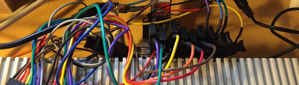
First, we need to add two additional wires in our hardware setup to connect the touch controller (see old wiring in last post) with the RPi:

Signal     Raspi      Display   Comment
T_IRQ      GPIO25       13       Interrupt line from ADS7846
T_CS       SPI0_CE0_N   11       SPI chip select 0

Software

I assume you already have a patched Linux kernel with the tft driver patches applied. Here is quick list with the next steps:

  • (Manually) apply dronus small patch to your kernel tree. This adds the necessary modifications of the ADS driver.
  • Note: I had to replace the invert_x with the invert_y entry in the ADS configuration to match the display orientation we use in the frame buffer driver
  • Your SPI config for the display now should look like this (for the newer *-9 display): linux/file arch/arm/mach-bcm2708/bcm2708.c
static struct ads7846_platform_data ads7846_config = {
  .x_max      = 0x0fff,
  .y_max      = 0x0fff,
  .x_plate_ohms    = 180,
  .pressure_max    = 255,
  .debounce_max    = 10,
  .debounce_tol    = 3,
  .debounce_rep    = 1,
  .gpio_pendown    = 25,
  .keep_vref_on    = 1,
  .swap_xy     = true,
  .invert_y    = true
};

static struct spi_board_info bcm2708_spi_devices[] = {
        {
                // ads7846 touchscreen on chipsel=0 device
                .modalias    = "ads7846",
                .bus_num    = 0,
                .chip_select    = 0,
                .max_speed_hz           = 500000,
                .irq      = GPIO_IRQ_START+25,
                .platform_data    = &ads7846_config,
                .mode = SPI_MODE_0
        }, {
                // display on chipsel=1 device
                .modalias = "ili9341fb",
                .max_speed_hz = 16000000,
                .bus_num = 0,
                .chip_select = 1,
                .mode = SPI_MODE_0,
                .platform_data = &(struct fbtft_platform_data) {
                        .gpios = (const struct fbtft_gpio []) {
                                { "reset", 23 },
                                { "led", 24 },
                                {},
                        },
                        .fps = 10
                }
        }
};
  • I use GPIO 25 for the touch IRQ (mainly because wiring was easier this way 🙂 and had to change the relevant entries. dronus used GPIO 17 instead.
  • I reduced the SPI rate of the display to 16 MHz and the frame rate to 10 fps. This proved to be more stable with activated touch controller.
  • The older -2 display works similarly. You only have to exchange the second block with the one of the r61505u driver. See old post for details
  • Open the configuration of the kernel and select the ADS driver:
> make menuconfig
Select "Device Drivers -> Input Device Support -> [*] Touchscreens -> [*] ADS7846..."
  • Make sure to include the ADS driver directly into the kernel and NOT in a module
  • Ok, thats it! (Re-)compile kernel and install it on your RPi…

Test

After a reboot your system shows a new input device in /dev/input/*. If no other USB mouse or keyboard is connected then the devices found there are all created by the touch controller.

You can use the evtest utility to check the touch operation (Install with ‘apt-get install evtest’ first!):

> evtest /dev/input/event0

When you tap on the display you will see the incoming events. Note the x and y coordinates mapping if you tap on different corners of the display.

Now with the basic operation tested you can start X11 on your display (see last post) and use your fingers or a stylus to navigate the mouse cursor!

Open Topic

While touch operation with this driver is rock solid and works very precisely I have found one little nuisance: I can’t move the X11 cursor into the border regions of the display 🙁 Approx 5 mm at the border of the visibile display area my touch movements are not recognized anymore and I can’t move the pointer there… I am not sure if this is a limitation of the display, of the ADS driver or the parameter set for the driver… If you find a workaround for this then please post a comment!

[Update: 21.4.2013] Pre-compiled Kernel

A pre-compiled Raspbian Wheezy Kernel 3.6.11+ with both ili9341 display and ads7846 touch driver (i.e. supporting all devices on the MI0283QT-9 board) is available for download here: